Introduction
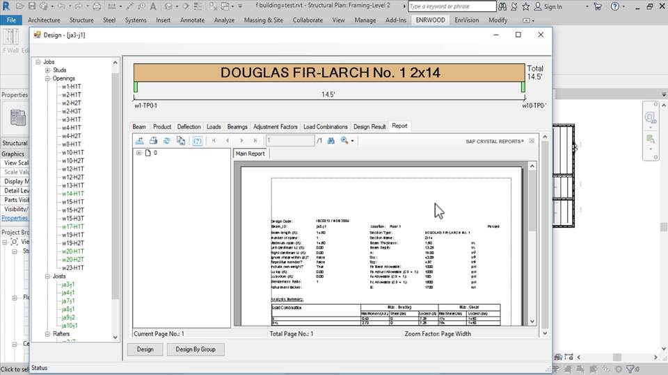
ENRWOOD for Revit is a Revit Add-on for wood/timber framing design.
ENRWOOD is a Building Information Modeling (BIM) based application. Objects (walls, openings, beams, posts, joists, and rafters) in BIM have physical, analytical, and behavioral properties.
- Easy to use with a simple user interface
- Accurate analysis results for all elements
- Optimized design selection
- Make your project in 3 clicks
Wall
Wall Framing
Create wall framing by following these steps:
- Select Revit wall or walls
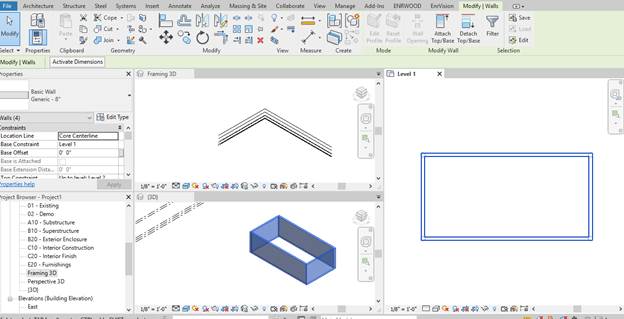
- Click the F Wall icon

- The wall framing data form will appear
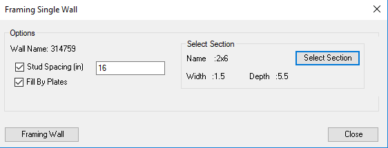
- Change the framing data in the form above
- Click Framing Wall button to apply framing
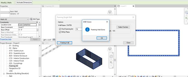
- Click Ok button
- Click Close button to close the form and command
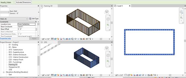
- Open Structural Plans
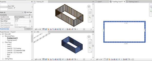
The framing is created automatically. The wall IDs and sections are generated.
Wall Reframing
Modification of wall geometry or adding an opening requires reframing the wall.
- Add windows and doors to your plan
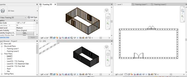
- Select Revit walls
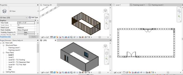
- Click the F Wall icon

- The wall framing data form will appear — change the data as needed
- Click Framing Wall button to apply framing
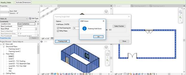
- Click Ok then Close
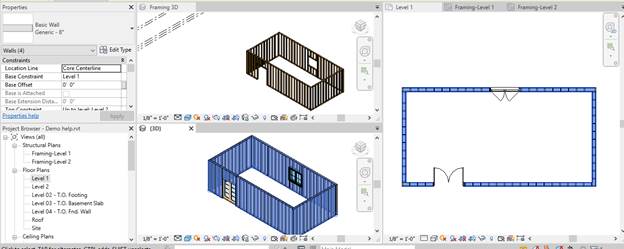
- Open Structural Plans
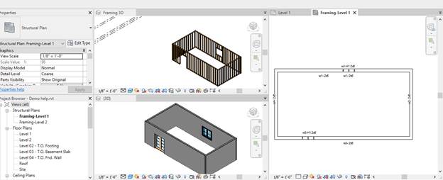
The framing is created automatically. The wall IDs/sections and header IDs/sections are generated.
Floor Joist
Joist Area Framing
Create Joist Area By Floor
- Select the floor

- Click the Floor Joist icon

- The framing of joist area form will appear
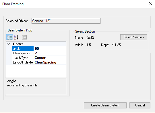
- Change the framing data in the form
- Click Create Beam System button to apply framing

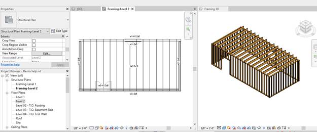
The framing is created automatically. Wall IDs/sections, header IDs/sections, and joist area IDs/sections are generated.
Create Joist Area By Draw Polygon
- Draw a polygon
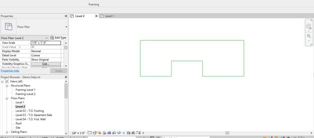
- Select the polygon
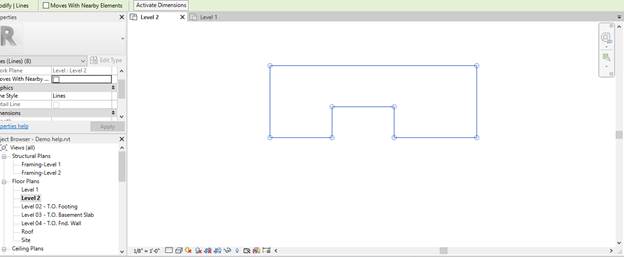
- Click the Floor Joist icon

- The framing of joist area form will appear
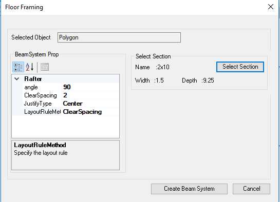
- Change the framing data in the form
- Click Create Beam System button to apply framing
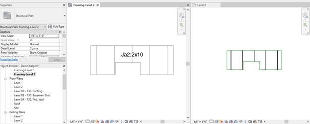
Create Joist Area By Select Boundaries
- Select boundaries
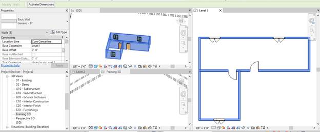
- Click the Floor Joist icon

- The framing of joist area form will appear
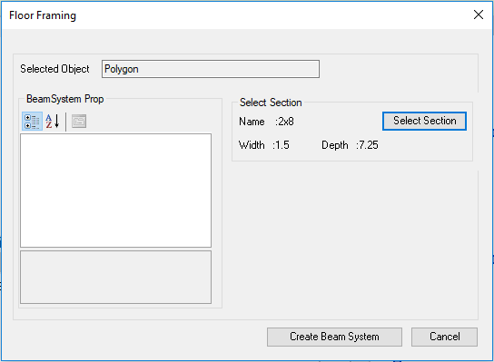
- Change the framing data in the form
- Click Create Beam System button to apply framing
Roof Rafter
Roof Rafter Framing
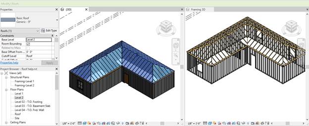
- Select the roof
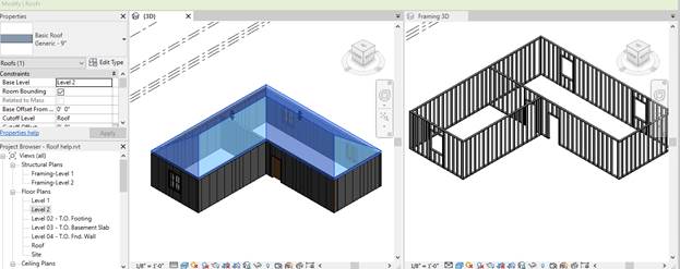
- Click Roof Rafter icon

- The roof framing form will appear
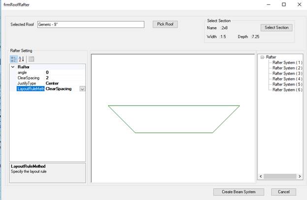
- Click Create Beam System to apply framing
Beam
Adding Beam
- Click the Beam icon

- The beam framing form will appear
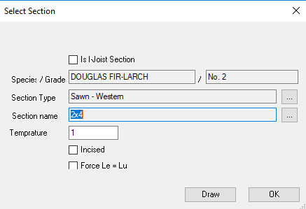
- Click Draw button
- Pick the start and end points of the beam
Post
Adding Post
- Click the Post icon

- The post framing form will appear
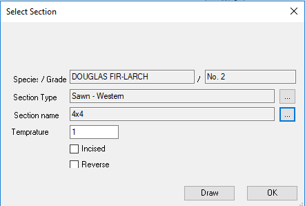
- Click Draw button
- Pick the center of the post
Framing Building
- Open the architectural model

- Click the F Building icon to create the framing
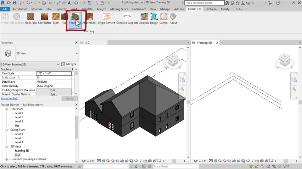
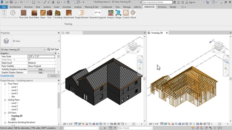
- The framing model is created
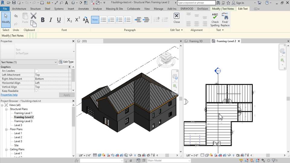
- 2D plan framing is also created automatically
Edit Section
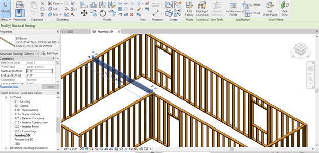
Edit Section of Beam / Post / Stud / Plate / Joist / Rafter
- Select the element
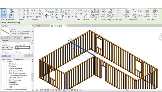
- Click Edit Section

- The section form will appear
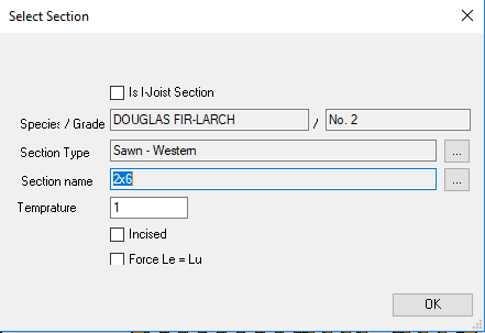
- Click the More
 button to open the section library
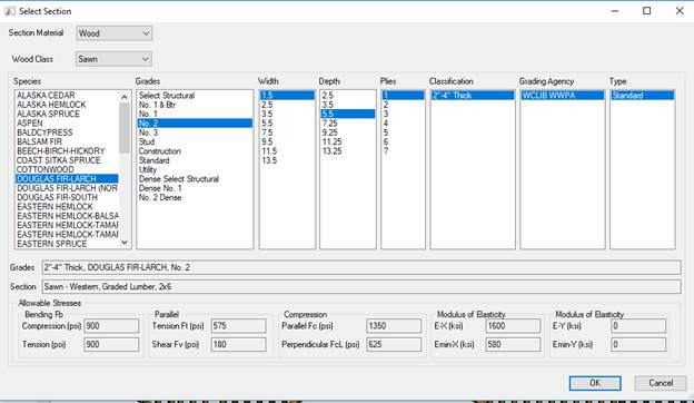
- Select a section and press Ok
Attachment
Wall Attachment
When there is a gap between walls and a joist area or roof rafter, Wall Attachment will fix it.
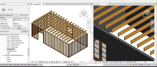
- Select wall or walls
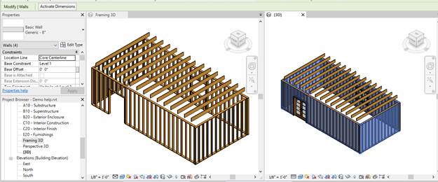
- Click the Attachment icon

- The attachment form will appear
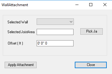
- Press Pick button, then select the joist area or roof rafter
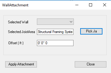
- Press Apply Attachment to apply
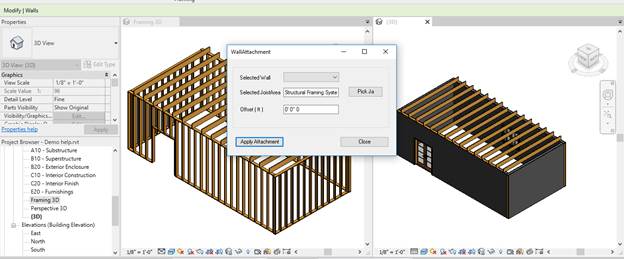
- Press Close to close the form
Beam Attachment
Use Beam Attachment to attach a beam to a joist area or roof rafter.
- Select the beam
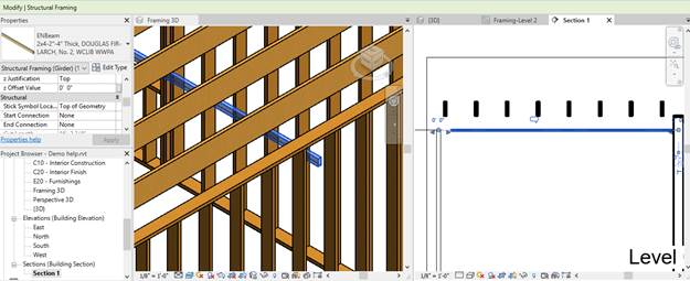
- Click the Attachment icon

- The attachment form will appear
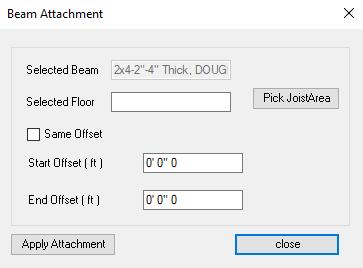
- Press Pick Joist Area button, then select the joist area
- Press Apply Attachment button
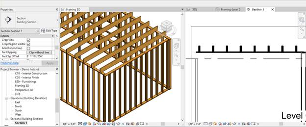
The attachment will be applied.
Generate Supports
- Generate supports for each element and set default loads by clicking the Generate Support icon

- Elements highlighted in red are unsupported
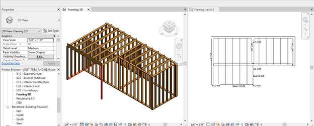
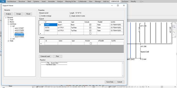
- Show element supports by clicking the Control icon and selecting an element

- The form shows element details
Loads
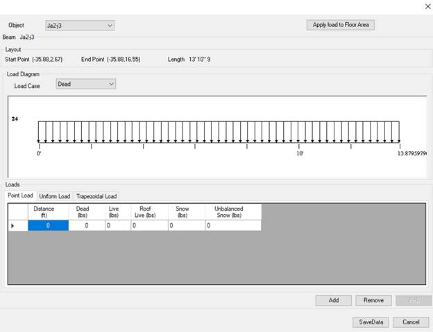
ENRWOOD supports both external and internal loads.
- Show element loads by clicking the Control icon and selecting an element

- Press External Loads to view default loads and modify external load values
Analysis Model
- To run the analysis, click the Analysis icon

- Each element will be solved and reactions transferred to its supports
Single Element
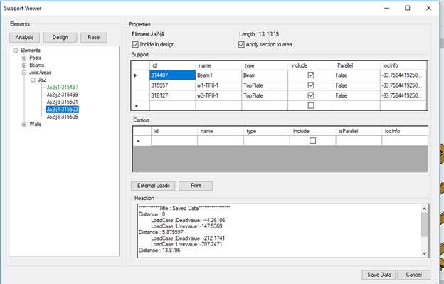
Single Element is an individual analysis mode — it carries analysis element by element.
- Click the Single Element icon

- Select the element
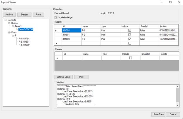
- The selected element and its supports will appear
- The selected element is solved and the reactions are transferred to its supports
Control
- Click the Control icon, then select an element

The form shows the following information:
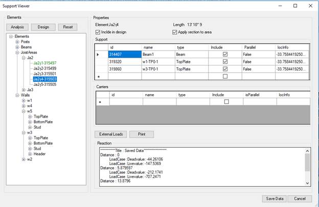
- Elements — Shows the tree of elements
- Support — Shows the selected element's supports. User can add or remove supports
- Carriers — Shows the elements supported by the selected element
- External Loads — Shows external loads of the selected element. User can add, remove, or delete loads
- Print — Shows the total loads (external and internal) of the selected element
- Reactions — Shows the reaction of the selected element
Include in design — Means the selected element will be included in the design process.
Apply section to area — For a joist area or rafter, the section will be applied to all joists or rafters in the area.
Analysis button — Runs analysis for each element in the tree.
Design button — Opens the design form.
Reset — Resets analysis data for each element in the tree.
Design Form
- Open the design form by clicking the Design icon

- The design process runs and the design form will appear
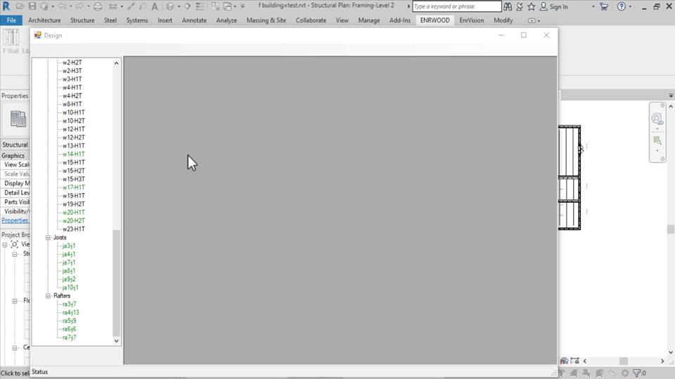
- Click an element name in the tree to open its design details
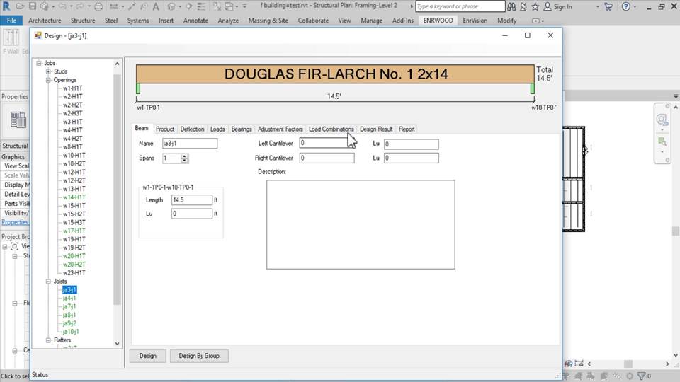
- Click the Design Result tab to view the design result
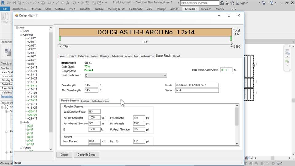
- Click the Report tab to view the design report