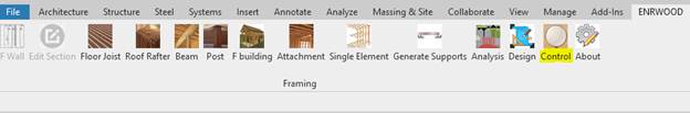
ENRWOOD - FRAMING
TABLE OF CONTENTS
·
Modeling
o
Wall
o
Beam
o
Post
·
Analysis
o
Loads
o
Control
·
Design
Introduction
ENRWOOD for
Revit is a Revit Add-on for wood/timber framing design.
ENRWOOD is a
Building Information Modeling (BIM) based application. Objects (walls,
openings, beams, post, joist and rafter) in BIM have physical, analytical and
behavioral properties.
ENRWOOD is
easy to use and simple user interface.
ENRWOOD is
accurate result of analysis elements.
ENRWOOD is
an optimized design selection.
Make your
project in 3 clicks.
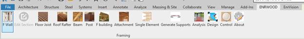
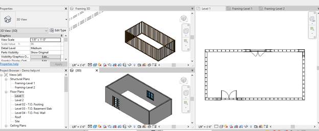
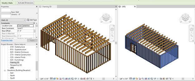
Wall
-
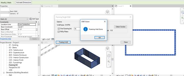
Wall Framing
Create wall framing by following
-
Select Revit wall or walls
-
Click “F Wall” icon
-
The wall framing data will appears
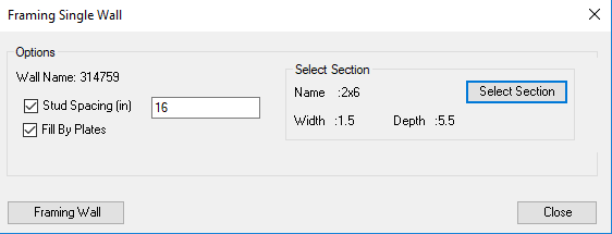
-
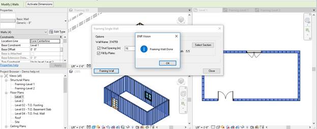
Change the farming data from above form.
-
Click “Framing Wall” button to applying framing
-
Click “ok” button
-
Click “Close” button to close form and command.
-
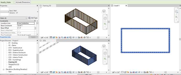
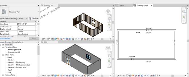
Opening “Structural Plans”
-
The framing was created automatically. The walls
ID/Section were generated
-
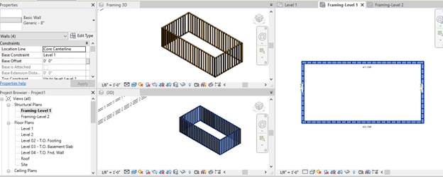
Wall Reframing
Modification wall geometry or adding opening, required
reframing wall
-
Adding window and door to our plan
-
Select Revit walls
-
Click “F Wall” icon

-
The wall framing data will appears
-
Change the farming data from above form.
-
Click “Framing Wall” button to applying framing
-
Click “ok” button
-
Click “Close” button to close form and command.
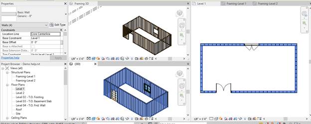
-
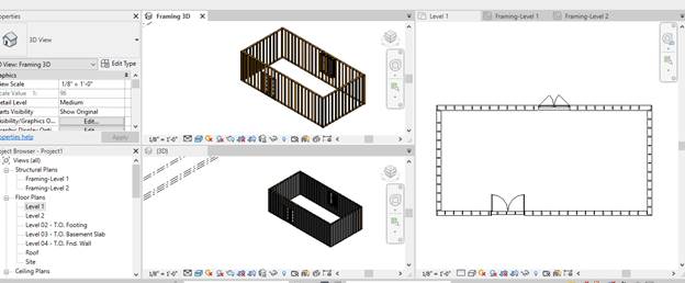
Opening “Structural Plans”
-
The framing was created automatically. The walls
id/section and headers ID/Section were generated
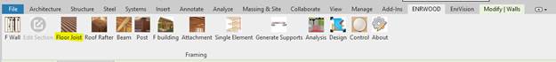
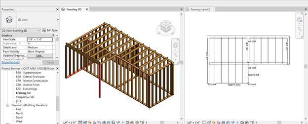
Floor Joist
-
Joist Area Framing
Create Joist Area By Floor
-
Select the floor

-
Click “Floor Joist” icon
-
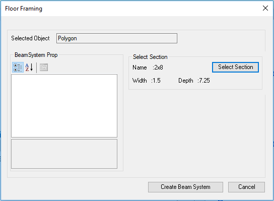
The framing of joist area form will appear.
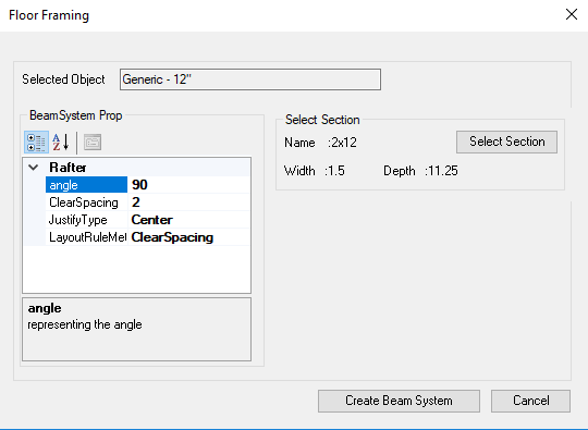
-
Change the farming data from above form.
-
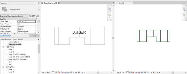
Click “Create Beam System” button to applying framing

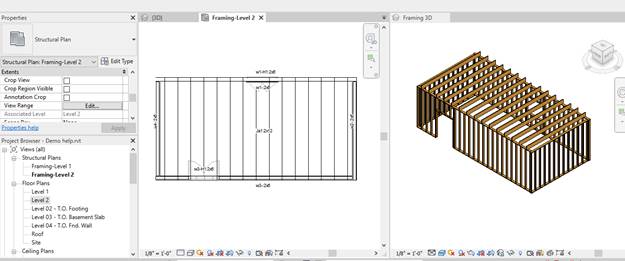
-
The framing was created automatically. The walls
ID/Section and headers ID/Section were generated. Joist Areas ID/Section were
generated.
Create Joist Area By Draw Polygon
-
Draw polygon
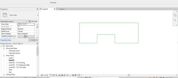
-
Select the polygon
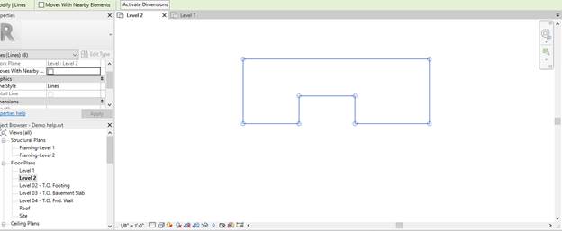
-
Click “Floor Joist” icon

-
The framing of joist area form will appear.
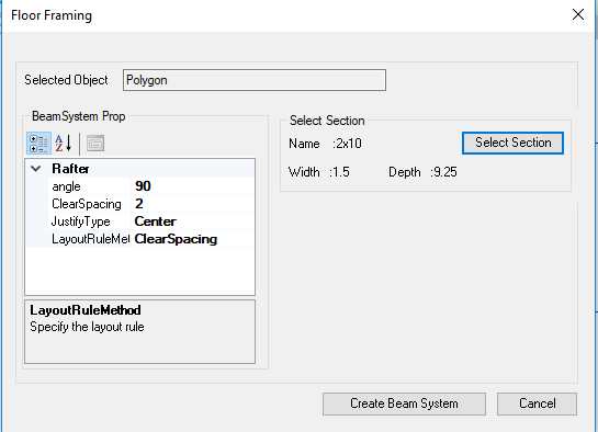
-
Change the farming data from above form.
-
Click “Create Beam System” button to applying framing
Create Joist Area By Select Boundaries
-
Select boundaries
-
Click “Floor Joist” icon

-
The framing of joist area form will appear.
-
Change the farming data from above form.
-
Click “Create Beam System” button to applying framing.
Roof Rafter
Roof Rafter Framing
-
Select The roof
-
Click “Roof Rafter
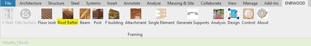
-
The form roof framing will appear
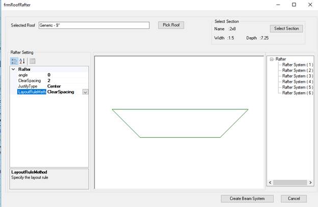
-
Click “Create Beam System” to applying framing.
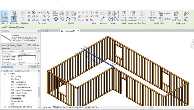
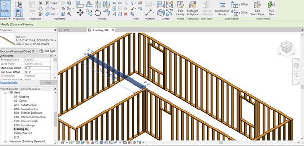
Beam
Adding
Beam
-
Click “Beam” icon
-
The beam framing will appear
-
Click “Draw” button
-
Pick start and end beam
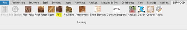
Post
Adding
Post
-
Click “Post” icon.
-
The post framing form will appear.
-
Click “Draw” button
-
Pick the center of post.
-
Note: the pick point is the bottom of post
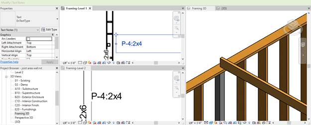
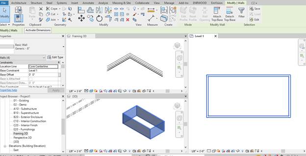
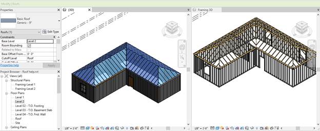
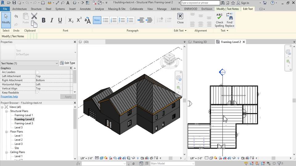
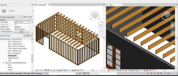
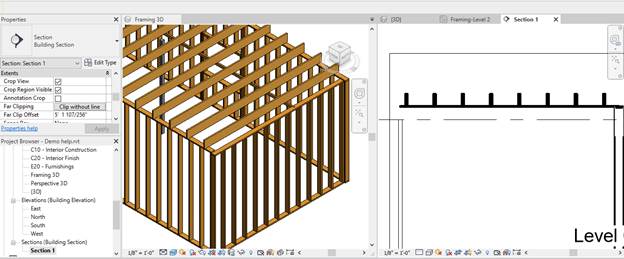
Framing building
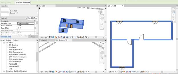
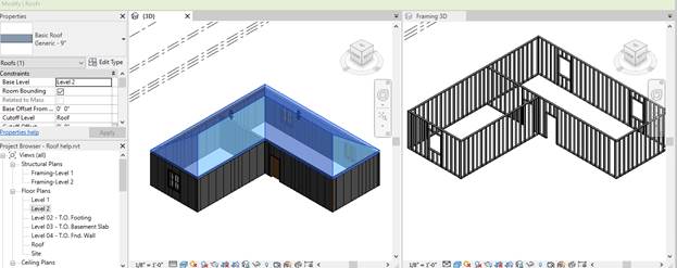
-
Open architectural model

-
Click open “F Building” icon to create the framing.
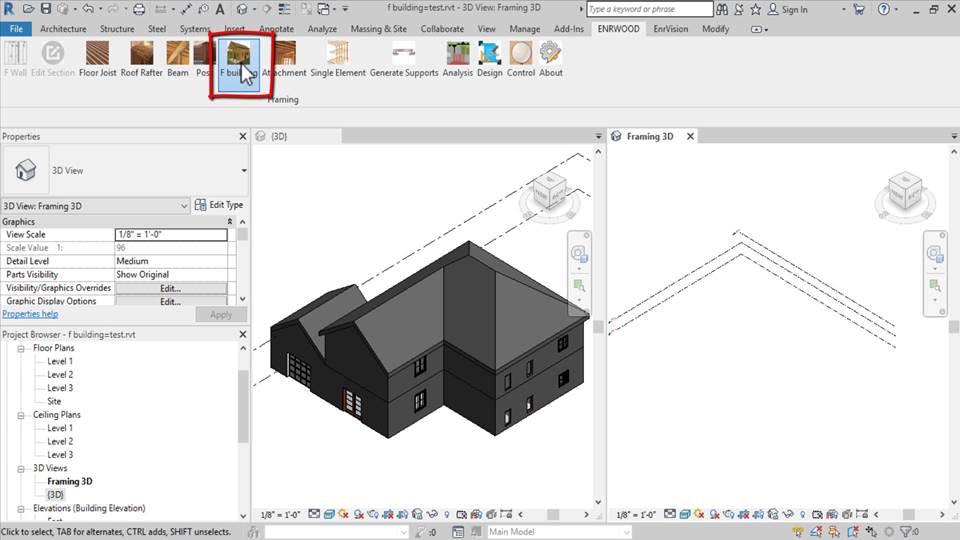
-
The framing model was created
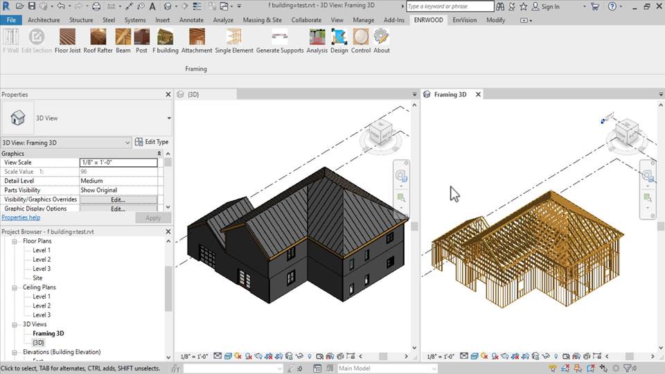
-
Also 2D plans framing was created
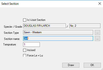
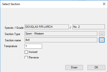
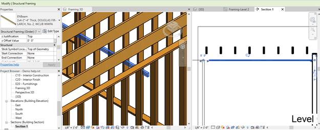
Edit Section
Edit Section Of Beam/Post/Stud/Plate/Joist/Rafter
-
Select element
-
Click “Edit Section”
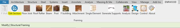
-
The form of section will appear
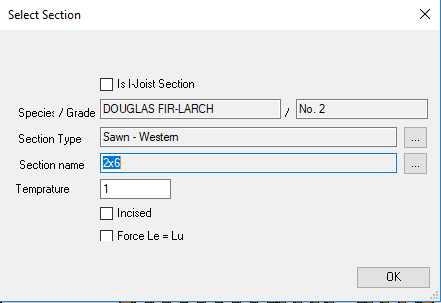
-
Click “More” ![]() button to open section library
button to open section library
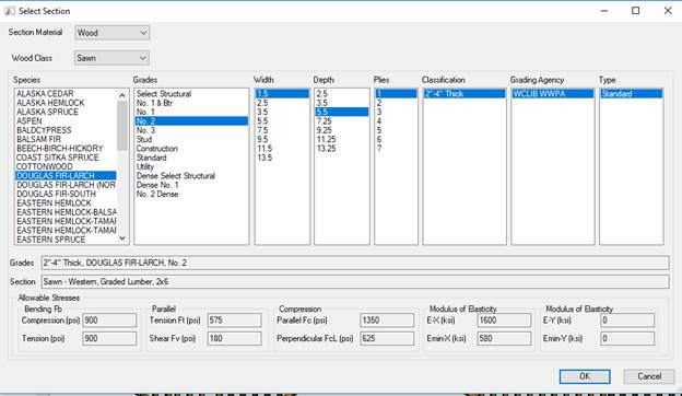
-
Select and press “Ok” button.
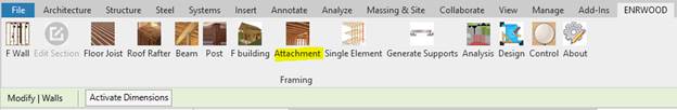
Attachment
Wall
Attachment
-
When there is a gap between walls and joist area/roof
rafter, wall attachment will fix it.
-
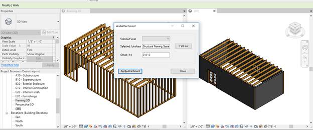
Select wall/walls
-
Click “Attachment” icon
-
The attachment form will appear
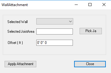
-
Press “Pick” button then select joist area/roof
rafter.
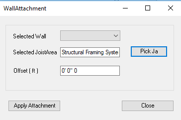
-
Press “Apply Attachment” to applying attachment.
-
Press “Close” button to close form.
Beam Attachment
To attaching beam to joist area/roof
rafter.
-
Select the beam
-
Click “Attachment” icon

-
The attachment form will appear
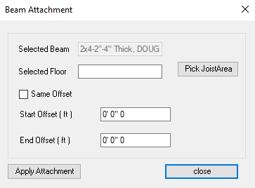
-
Press “Pick Joist Area” button
-
Then select joist area and Press “apply Attachment”
button
-
The attachment will be applied.
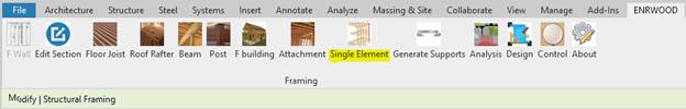
Generate Supports
-
Generating supports for each elements and default
loads by Click “Generate Support” icon.

-
Red color means unsupported element.
-
Show element supports by click “Control” icon and
select element.
-
The form shows element details
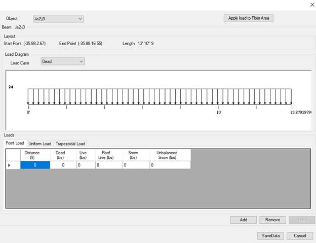
Loads
There are external and internal
-
Show element loads by click “Control” icon and select
element.


-
Press “external loads” to see default loads and
modifying external load
Analysis Model
-
To run the analysis, click the “Analysis” icon.
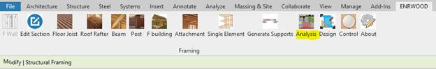
- Each element will be solved and transferring reactions to its supports.
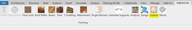
Single Element
It is individual analysis. Carrying
analysis element by element.
-
Click the “Single Element” icon
-
Select the element
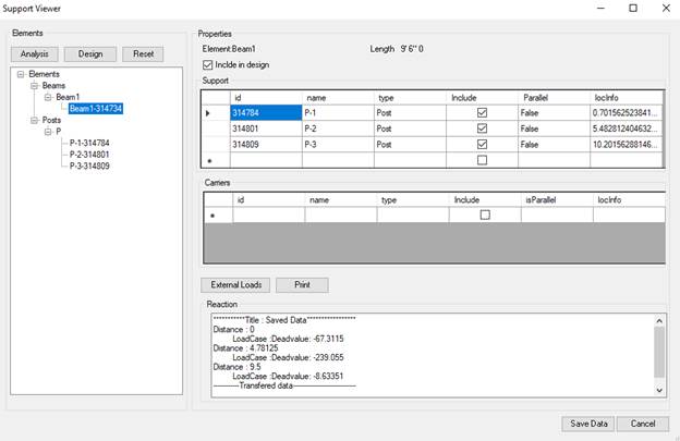
-
The Selected element and its supports will be appeared
-
The selected element is solved and the reactions are
transferred to supports
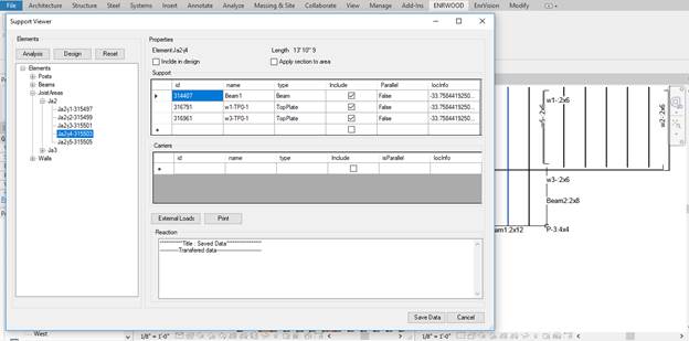
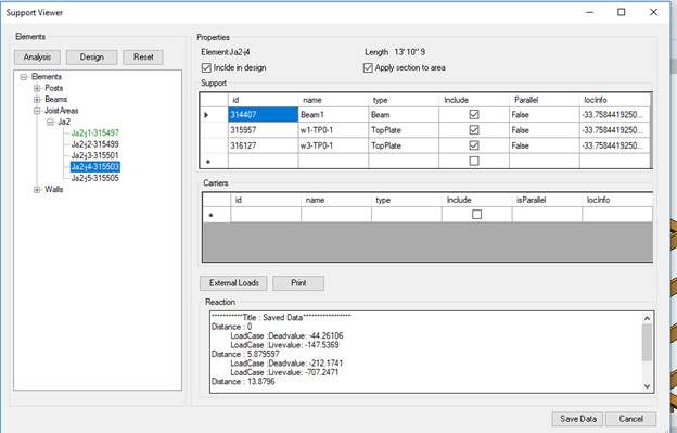
Control
-
Click the “Control “icon and then select element.
The form shows the following
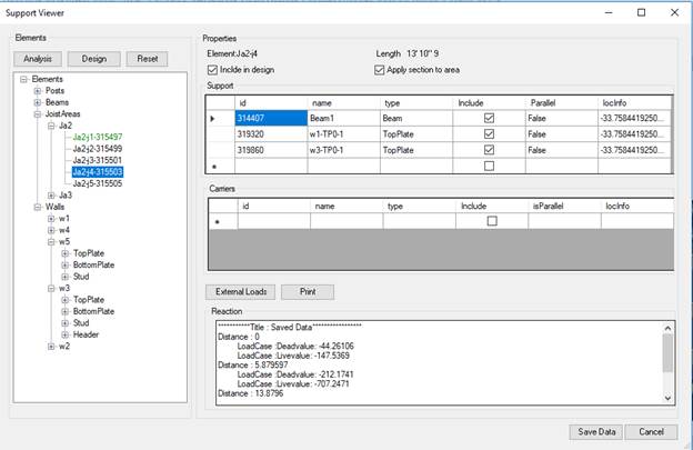
-
Elements:
o
Shows the tree of elements.
-
Support:
o
Shows the select element supports. User can add/remove
supports
-
Carriers:
o
Shows the elements supported by the select element.
-
External Loads:
o
Shows the external load of selected element. User can
add/remove and delete the loads.
-
Print:
o
Shows the total loads (external and internal) of the
selected element.
-
Reactions:
o
Shows the reaction of the selected element.
Include in design:
Means the selected element will
included in design process.
Apply section to area:
This for a joist
area/rafter, means the section will applied to all joists/rafters
The “Analysis” button:
Run analysis for each
element in the tree.
The “Design” Button:
Open design form.
The “Reset”:
Reset data of analysis
for each element in the tree
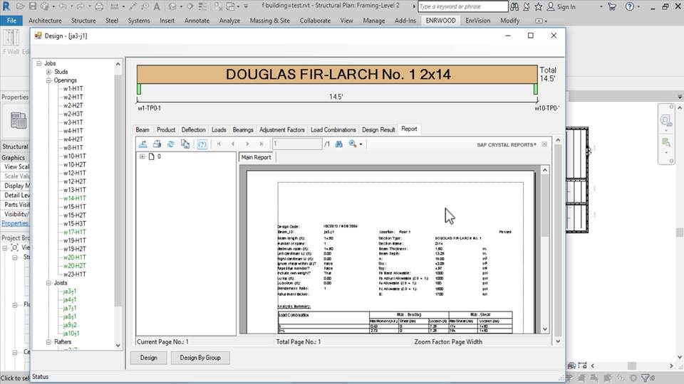
Design Form
- Opening design form by click the “Design” icon.
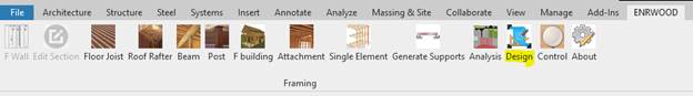
-
The design process is running and the design form will
appear.
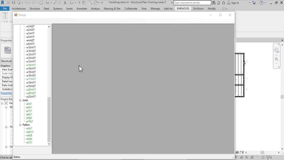
-
Click the element name in tree to open design details
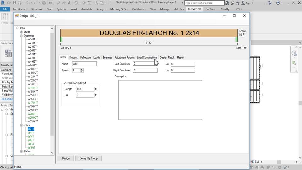
-
Click “Design Result” tab to see the design result
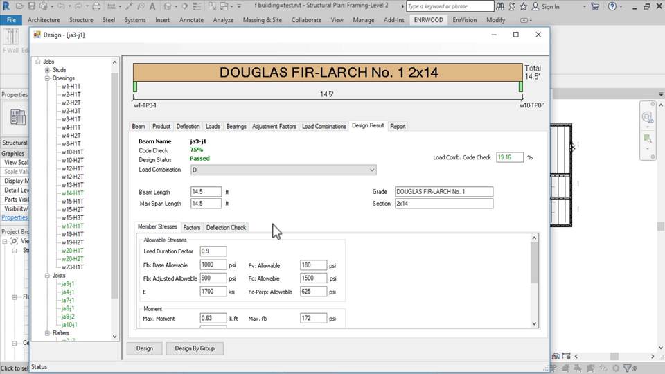
Click “Report
“ tab to view design report